Difference between revisions of "Filter Modulator build"
| Line 27: | Line 27: | ||
Then simply checkout and pay Digikey and it will automatically order all the parts you require to construct the board which will arrive bagged up marked with circuit references. This is the recommended way to order your parts if you decide to build the board yourself, but you can of course order the parts from your own supplier. | Then simply checkout and pay Digikey and it will automatically order all the parts you require to construct the board which will arrive bagged up marked with circuit references. This is the recommended way to order your parts if you decide to build the board yourself, but you can of course order the parts from your own supplier. | ||
| + | |||
| + | ===Board versions=== | ||
| + | |||
| + | PCBs supplied before 15 March 2017 are Version 1. | ||
| + | |||
| + | Assembled PCBs due to be supplied in March 2017 will be at Version 1A (modified Version 1). | ||
| + | |||
| + | Any blank PCBs delivered after 15 March 2017 will be at Version 2 (more details to follow). | ||
===Board information - version 1=== | ===Board information - version 1=== | ||
| Line 58: | Line 66: | ||
These modifications bring the board to "Version 1A" standard and are described here [[Filter Modulator Version 1A Modifications]]. | These modifications bring the board to "Version 1A" standard and are described here [[Filter Modulator Version 1A Modifications]]. | ||
| − | |||
| − | |||
| − | |||
| − | |||
| − | |||
| − | |||
| − | |||
===Soldering the Small ICs=== | ===Soldering the Small ICs=== | ||
Revision as of 10:55, 22 March 2017
There are 2 ways to get a Portsdown filter modulator board - ready built and tested Portsdown modulator boards will be available from the BATC shop This is the easiest way to get one - current estimate for delivery is early to mid March 2017 .

Each assembled board comes with it's own test report and what next instructions - see File:FM Check Sheet v2a.pdf
For those wanting to construct the board themselves, the blank PCB is available from the BATC shop
Note: Building the board is not a beginner's construction project as the PCB contains 129 surface mount parts including ICs in dense packages. If you are not used to SMD assembly, we suggest you buy the assembled PCB from the BATC shop.
Parts List
Below is a bare bones parts list, or Bill of Materials, as an .xls file which you can upload to Digikey.
If you wish to make any changes such as select the larger heatsink option, use an external regulator, a different heatsink or delete components you already have, simply amend the item in the "Quantity" column before uploading to Digikey.
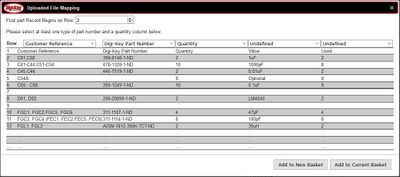
To use the facility, sign in to digikey (you will need to register first) and go to my basket and follow these instructions. You then need to make the following changes:
- Change the "First part Record begins on Row" to "2"
- Use the column drop down boxes to match the first 3 column titles to the .xls file. Note the final 2 columns are for your reference only - on some tape and reel components you are ordering more parts than required as this is the most economical price break - you can change these in the .xls if you require but Digikey will then mark them as a query item.
Once finished the Portsdown BoM should look like this:

Then simply checkout and pay Digikey and it will automatically order all the parts you require to construct the board which will arrive bagged up marked with circuit references. This is the recommended way to order your parts if you decide to build the board yourself, but you can of course order the parts from your own supplier.
Board versions
PCBs supplied before 15 March 2017 are Version 1.
Assembled PCBs due to be supplied in March 2017 will be at Version 1A (modified Version 1).
Any blank PCBs delivered after 15 March 2017 will be at Version 2 (more details to follow).
Board information - version 1
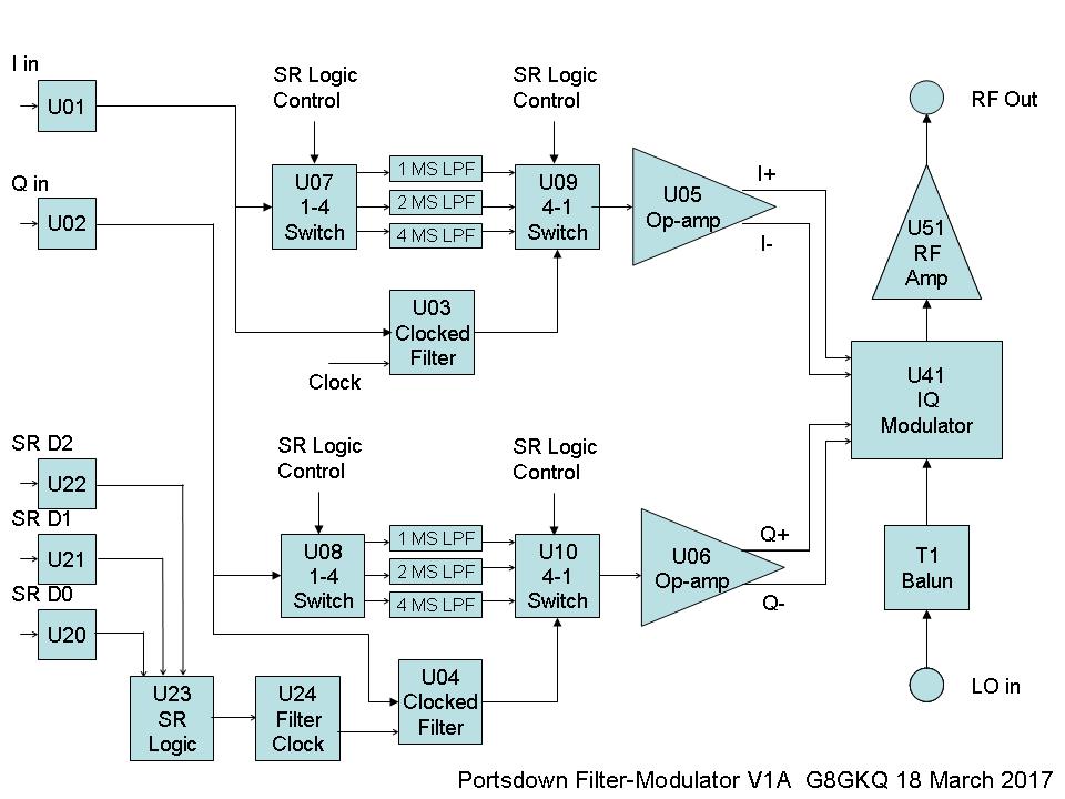
PCBs supplied before 28 February 2017 are Version 1 and the parts list and schematics are available for download:
These diagrams do not reflect the minor circuit changes for V1a, so read the information below.
Modifications to Improve the Transmitted Spectrum on Version 1 Boards
The Version 1 boards described above are OK to use on-air as any spurious emissions are about 50 dB below the main transmission, and the modulation "shoulders" will generally be in-band. However there are a few modifications that can be done to improve their output and reduce the level of the "shoulders" at SR1000 and above. The modifications also equalise the levels between low SRs (RB-TV) and higher SRs (1000 and above).
These modifications bring the board to "Version 1A" standard and are described here Filter Modulator Version 1A Modifications.
Soldering the Small ICs
Colin G4KLB has a done a short video showing how to solder the small ICs on to the board - it's available on the BATC Youtube channel here.
Testing the board
Once you've completed building your own board you will have to test it - we're currently working out the process but the outline will be something along these lines. These procedures assume that you have completed the board and fitted the 5V regulator either to the heatsink on the board, or to an external heatsink.
Do not connect any other modules to start with.
- Using a variable power supply, with a current monitor in circuit, slowly wind up the supply voltage to the regulator, monitoring the 5V rail (on the output of the regulator). The 5V rail should stabilise at 5V as the supply to the regulator is increased above 7V. The supply current should be about 250 mA (+/- 50 mA). If the 5V rail goes above 5.2V, or the supply current is greater than 300 mA, stop the process and look for faults on the board.
- Make sure that your ADF4351 is working with your RPi. Select IQ output mode and transmit, and you should be able to receive the carrier on a receiver or measure the frequency with a counter. Then connect the ADF4351 output directly to the filter modulator input.
- If all is well with the DC tests and the ADF4351, connect your filter modulator board to the RPi. Make sure that you connect the signal and return lines for both I and Q signals and the filter select lines, as these are isolated from the ground on the filter modulator board.
- Set the RPi to transmit on 1255 MHz at 2MS. Make sure that you have the output mode set to IQ. Set up a receiver (preferably MiniTioune, but a Satellite receiver will work) to receive these parameters.
- Turn the RPi on and set it to transmit. You should see a signal on your receiver. If you do not see an increase in signal level, check the output of the ADF4351, and then the output of the filter/modulator. The filter/modulator output should be greater than 4 dBm (4 mW) at 1255 MHz.
- If you get a signal, but it is not decoding, check the following in order:
- There should be 3.3v p-p 1 MHz (approx) data signals on J01 pins 2 and 4, and J01 pins 1 and 3 should be at ground.
- There should be similar 5V p-p data signals on the hot ends of R03 and R04.
- There should be 0.6v p-p signals on each of the test points I+, I-, Q+, Q- near U41.
- If the I and Q signals are not present, check the DC switching of the SR filters on J02.
- Adjust the balance pots – Select test signal from the console "Source" menu. Place a voltmeter between the I+ and I- test points and adjust RV1 for 0 Volts. Repeat for Q+ and Q- adjusting RV2.

- Do not forget that you may need to rescan for new signals on a Satellite receiver.
- If you have a MiniTiouner system, check the MER readings and make final balance adjustments.
We are currently working out how to check for correct RF level output but there are some very interesting devices appearing on eBay - search for "RF power meter".